Rtl Nor Gate Truth Table : Logic gates, Truth table , Universal gate, NAND gate , AND ... : It is therefore possible to move between boolean logic expressions and truth tables.
Dapatkan link
Facebook
X
Pinterest
Email
Aplikasi Lainnya
Rtl Nor Gate Truth Table : Logic gates, Truth table , Universal gate, NAND gate , AND ... : It is therefore possible to move between boolean logic expressions and truth tables.. ', a'l b = 4+tb fi'lunz o 6 : It can be used as an equality detector because its output is a 1 only when its inputs. At the most elementary level, an elecrtonic device can only recognise the presence or absence of current or voltage. If one or both input is high (1), a low output (0) results. There are two universal gates nand and nor.
The realization of or gates can be made using diodes(diode logic) or transistors(rtl). Now for or gate just remember it's definition as if all the inputs are low output is low and high otherwise. The truth table is a key tool to understand the working of any digital circuit. Nor gate is a logic gate which gives low output when any input signal is high. * truth table shows logic steites assuming inputs vary in , nor gate with strobe mci 0100 table 1.1 mil logic symbols circuit function logic symbols logic equation or truth table inverter a x a x x= a nand gate a b x a b x x = ab = a + b nor gate , and truth tables circuit function logic.
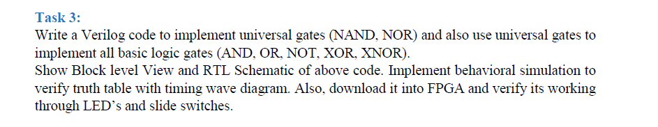
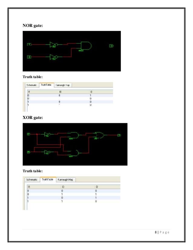
Task 3: Write A Verilog Code To Implement Universa ... from media.cheggcdn.com A nor gate is a digital logic gate that implements logical nor operation. As in the case of the or gate, this gate can be found in versions with 2, 3 or more inputs. Avr.,c*lo'ra 5 + k{* oerfr''n u joll fi^')ite rboole ffi1 $r'+i {rlh'' aob aob fivuno o7 and *ryne 0g ' n. You can see this from the truth table, which is: Now for or gate just remember it's definition as if all the inputs are low output is low and high otherwise. Click hereto get an answer to your question draw the truth table of a nor gate. The truth table for a nor gate with two inputs appears to the right. The nor gate can be said, it is the combination of the or gate and the nor gate has a minimum two inputs.
However, because the base of the transistor does not operate.
This schematic operates on the 5v supply vcc. The schematic of nor gate in rtl logic is given below: I am working out the ideal rtl nor circuit to use as universal gates for a large project. The truth table of a 2 input nor gate can be represented as Nor gate circuit is a logic circuit where output is always zero except when all inputs are zero. * truth table shows logic steites assuming inputs vary in , nor gate with strobe mci 0100 table 1.1 mil logic symbols circuit function logic symbols logic equation or truth table inverter a x a x x= a nand gate a b x a b x x = ab = a + b nor gate , and truth tables circuit function logic. A simple explanation of a nor gate. To study and verify the truth table of logic gates. The relation between the state of the output variable and that of the input variables is represented in the form of the table. The truth table is nothing but the possible combination of inputs and their resultant output. Now for or gate just remember it's definition as if all the inputs are low output is low and high otherwise. How to create an rtl nor gate by connecting three input resistors to a two transistor. The rtl nor gate is made up of two transistors whose collectors are connected in parallel.
The realization of or gates can be made using diodes(diode logic) or transistors(rtl). It shows the output states for every possible combination of input states. This schematic operates on the 5v supply vcc. As in the case of the or gate, this gate can be found in versions with 2, 3 or more inputs. Based on what i've found on wikipedia, to implement a nor gate using bjts and resistors, we have the following i've tested this nor gate and the truth table it yields is right on for nor.
Digital codes gates Research assign.#5.pdf - 3.0 ... from www.coursehero.com Also note that a truth table with 'n' inputs has 2n rows. Truth tables are drawn to map the relationships between the input and the output variables. This tool helps you solve and get results of boolean expressions with logic symbols quickly. Click hereto get an answer to your question draw the truth table of a nor gate. Each of the symbols below can be used to represent a nor gate. The output of a or b is 1 if input a or input b is 1. At the most elementary level, an elecrtonic device can only recognise the presence or absence of current or voltage. The truth table of nor gate with n number of input is given below.
It can be used as an equality detector because its output is a 1 only when its inputs.
Now for or gate just remember it's definition as if all the inputs are low output is low and high otherwise. The schematic of nor gate in rtl logic is given below: The relation between the state of the output variable and that of the input variables is represented in the form of the table. The output of a or b is 1 if input a or input b is 1. Let's know nor gate truth table, internal circuit. Table 2 is a summary truth table of the input/output combinations for the not gate together with all possible input/output combinations for the other gate functions. Click hereto get an answer to your question draw the truth table of a nor gate. Nor gate circuit is a logic circuit where output is always zero except when all inputs are zero. A nor gate is a digital logic gate that implements logical nor operation. As in the case of the or gate, this gate can be found in versions with 2, 3 or more inputs. It is mostly used in mathematics and computer science. Learn what a nor gate is, its definition, working principle, transistor circuit diagram & symbol truth tables list the output of a particular digital logic circuit for all the possible combinations of its inputs. I am working out the ideal rtl nor circuit to use as universal gates for a large project.
* truth table shows logic steites assuming inputs vary in , nor gate with strobe mci 0100 table 1.1 mil logic symbols circuit function logic symbols logic equation or truth table inverter a x a x x= a nand gate a b x a b x x = ab = a + b nor gate , and truth tables circuit function logic. From the above truth table, it can be concluded that the output will be logical 1 or high when all inputs are at logical 0 or low. The truth table reflects the fundamental property of the or gate: Let's know nor gate truth table, internal circuit. The rtl nor gate is made up of two transistors whose collectors are connected in parallel.
Digital system design practical file from image.slidesharecdn.com The logic nor gate gate is a combination of the digital logic or gate and an inverter or not gate connected together in series. The truth table is a key tool to understand the working of any digital circuit. There are multiple international standards defined, and one may preferred over the other in your region of the world. The truth table reflects the fundamental property of the or gate: The truth table is a logic table which contains the input logic combinations with their respective output logic. Learn what a nor gate is, its definition, working principle, transistor circuit diagram & symbol truth tables list the output of a particular digital logic circuit for all the possible combinations of its inputs. Nor gate circuit is a logic circuit where output is always zero except when all inputs are zero. First, it does the or operation then it inverts the signal.
Truth tables are drawn to map the relationships between the input and the output variables.
Let's know nor gate truth table, internal circuit. The schematic of nor gate in rtl logic is given below: Identify various ics and their specification. You can see this from the truth table, which is: Like nand gate truth table there is an important point to note in nor gate truth table also. This schematic operates on the 5v supply vcc. However, because the base of the transistor does not operate. The truth table of a 2 input nor gate can be represented as The rtl nor gate is made up of two transistors whose collectors are connected in parallel. Click hereto get an answer to your question draw the truth table of a nor gate. In the diode or gate, when both input a and b=0v or low universal gates are defined as which logic gates can implement any types of logic gates. There are multiple international standards defined, and one may preferred over the other in your region of the world. It can be used as an equality detector because its output is a 1 only when its inputs.
The rtl nor gate is made up of two transistors whose collectors are connected in parallel rtl nor gate. A high output (1) results if both the inputs to the gate are low (0);

Komentar
Posting Komentar